
If an electrical problem occurs, the computer will enter a limp-in mode. A warning light on the dash will start flashing and the transaxle can only be shifted manually in third, fourth and reverse.
T
he AW50-42LE transaxle appears in Volvo's 850. Although this unit isn't new on the scene (it was introduced in 1992), it is new to most rebuilders. Why? Because the lack of any meaningful technical information has made this unit almost impossible to fix. A lot of important information, such as oil flow charts are still lacking, but we now have some computer testing information that will help you resolve outside electrical problems. But first, let's cover a little background information on this unit.
The AW50-42LE uses a compound planetary on the primary shaft and a single planetary on a secondary shaft. A gear on the secondary shaft drives the differential ring gear. The torque converter includes a lockup clutch. This arrangement provides four forward gears and one reverse. Operation and view of transaxle appears in figures one and two.
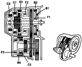
Figure 1
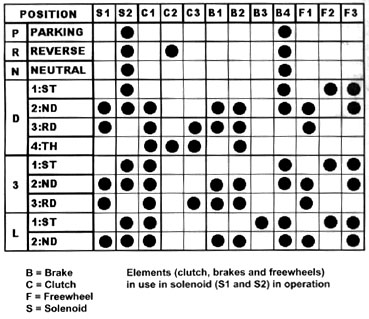
Figure 2
A transaxle control unit (computer), located in the engine compartment, controls shift timing, lockup and line pressure rise (figure 3) sport-economy button varies shift timing. It also has a winter button, which forces the transaxle to start in third gear to reduce tire slip on icy roads.
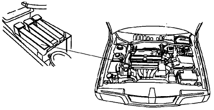
Figure 3
If an electrical problem occurs, the computer will enter a limp-in mode. A warning light on the dash will start flashing and the transaxle can only be shifted manually in third, fourth and reverse.
1992Ł95 models have an underhood diagnostic unit that provides five diagnostic test modes (DTMs) which enable you to retrieve trouble codes, check switch operation, activate solenoids and warning lights, and monitor sensor data. Unfortunately, 1996 and later models don't have this feature; you'll need a scan tool to operate onboard diagnostics. So the diagnostic information in this article will only cover models between 1992 and '95.
First, locate the diagnostic controller behind the right headlight (figure 4). At the top of the diagnostic controller is a button for controlling the system, and an LED for output display. All communications to and from the computer can be controlled through this button and LED (there's also a diagnostic connector for a scan tool, on the console, but good luck finding a scan tool for it). Also, notice there are six sockets on the diagnostic controller. If you want transmission functions, you'll need to connect the diagnostic lead to socket one.
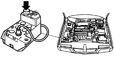
Figure 4
The LED outputs a series of three flash groups. For example, a certain function may report results by flashing twice, then five times, then four times (2Ł5Ł4). The meaning of this flash sequence depends on which diagnostic function you're performing. To determine that meaning, you simply look up that sequence in the chart for that function.
To enter a command, such as 4-2-4 (in test function five), you would enter the diagnostic routine, then wait for the computer to respond by flashing the LED. You then press the button four times, and wait for the computer to acknowledge by it flashing the LED once. Then you'd press the button twice, and wait for the LED flash. Finally, you'd press the button four times. This sequence tells the computer that you want it to report VSS output in miles per hour.
All tests are performed in a similar fashion. The codes and sequence flashes are shown in the various charts, following the DTM procedures.
The five diagnostic test modes (DTMs) are:
DTM One: Retrieving and Erasing Trouble Codes
To retrieve codes:
The computer can store up to five codes. Use the chart in figure five to identify codes.
After displaying trouble codes, you must turn off the key before starting the engine.
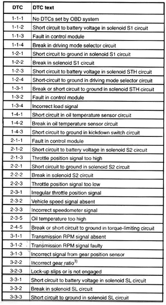
Figure 5
To erase codes:
DTM Two: Checking Switch Operation
If correct response codes appear, the switches are working properly. If not, replace or repair the switch circuits as necessary.
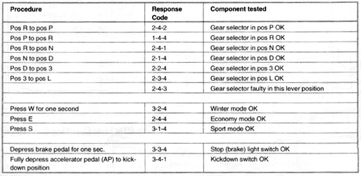
Figure 6
DTM Three: Checking Solenoid and Computer Operation
During this test, the computer will activate each solenoid or computer function six times. Observe solenoid clicking, engine speed change or warning light flashing during this test. Each solenoid and computer function is tested in this order:
* Engine speed will change during self testing.
After the transmission computer operates a solenoid or performs a function six times, there will be a short pause. Then the computer will operate the next device on the list. After the entire cycle repeats three times, the test stops automatically. If any solenoid or computer function failed to work correctly, check the related circuits and components.
DTM Four: Checking Specific Solenoid and Computer Operation
To enter this test:
When test is in progress, the LED will flash. After the solenoid or computer function is activated six times, the test will stop automatically. If necessary, repeat the test, or continue testing other solenoids or computer functions.
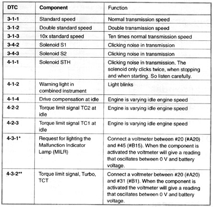
Figure 7
DTM Five: Checking Current Input Sensor Data
This test allows you to monitor the transmission oil temperature, vehicle speed, transmission RPM and throttle sensor position while the vehicle is in operation. The data is displayed by watching the LED blink a code: This is called the response code. This response code is converted to the appropriate specification, depending on which table is used.
To enter this test:
The LED will then flash the response code for the status of the sensor being tested. Use the appropriate conversion table to obtain the operating specification as shown in figures eight, nine and ten.
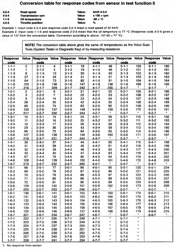
Figure 8
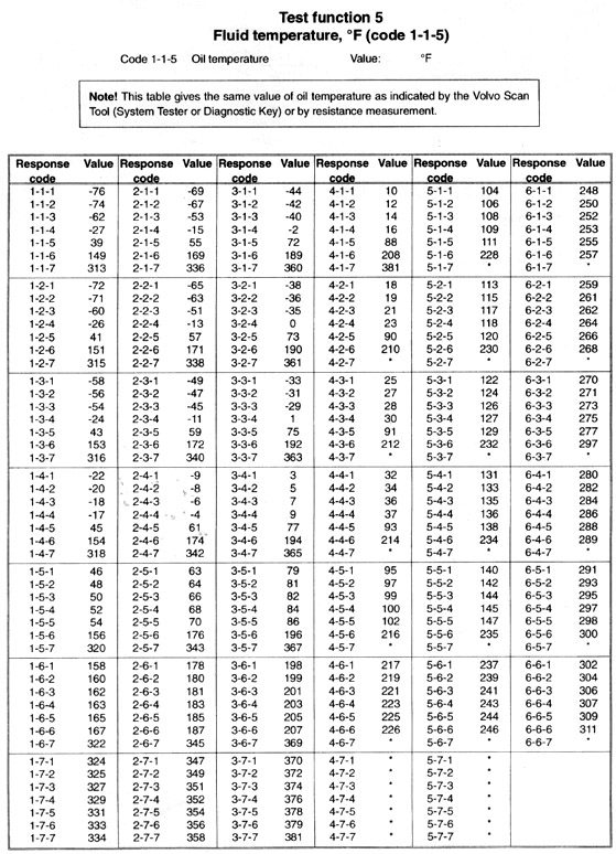
Figure 9
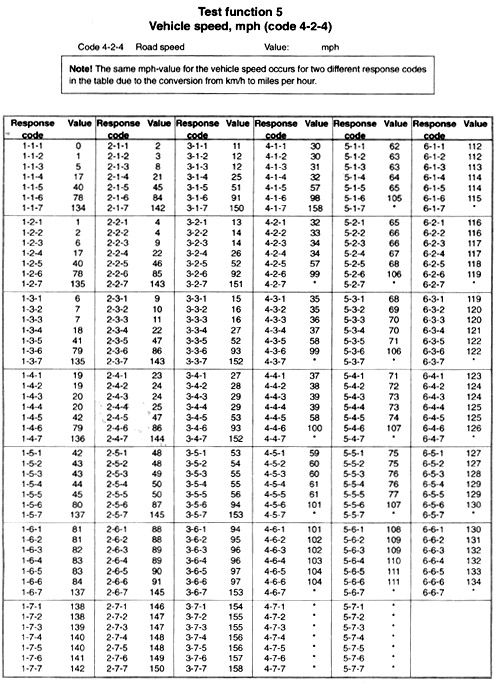
Figure 10
Working on Volvo's AW50-42LE is still not a task for the weak at heart. For most shops, it's probably not a job they want to tackle. But as more information becomes available, it gets a little easier.
![]()