
Q
. We're working on a 1992 Eclipse equipped with a KM175. While measuring the pressure control solenoid signal with my meter, I notice it doesn't change duty cycle with throttle opening. I know the solenoid only functions during the shifts and then turns off, but shouldn't the duty cycle change with throttle opening? I also noticed that if I measure the signal in DC volts, the voltage level does vary with throttle. What am I doing wrong?A
. The duty cycle does change with throttle, but the waveform is somewhat complex, and essentially confuses your meter. This system operates the pressure control solenoid using a "current limiting" circuit.Figures one
and two show two Mitsubishi pressure control solenoid waveforms. The first is at light throttle, the second at heavier throttle. Notice that both waveforms have an initial 12-volt apply: This is where the computer momentarily applies full system voltage, just to open the solenoid. But the solenoid requires far less current to stay open than it does to open initially. So the computer drops the signal down to three volts. This three volts is what holds the solenoid open throughout its on-time, and it's how the computer limits the current to the solenoid. Finally the computer turns off the three-volt signal, until the cycle begins again.
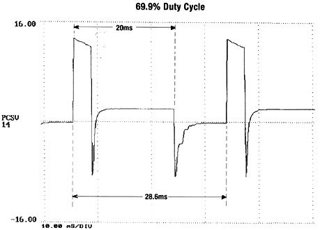
Figure 1
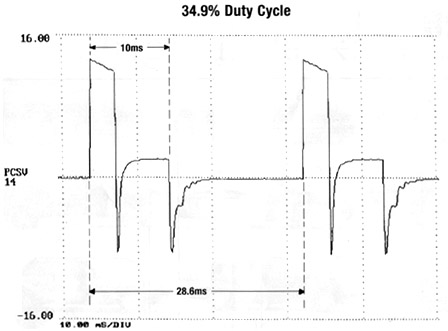
Figure 2
The duration of the 12-volt spike is the same for each cycle--the computer controls the duty cycle by adjusting the duration of the
three-volt signal. But your meter doesn't know this: When set to measure duty cycle, it only looks for the duration of the 12-volt portion of the signal, and compares that to the rest of the cycle. Since the duration of the 12-volt signal doesn't change, the meter reports that the duty cycle doesn't change, either. The actual on-time begins with the 12-volt spike, and goes to the end of the three-volt signal. If you want an accurate measurement of duty cycle, you'll need to measure the combined duration of the 12-volt and the three-volt portions of the signal, and compare them to one complete cycle (on-time plus off-time). For that, you'll need a scope.With that in mind let's refer back to figures one and two and figure out the duty cycle for these two waveforms. Before we begin, let's cover a few terms:
Mitsubishis operate their pressure control solenoid at 35 Hz. Period is a reciprocal of frequency, so 1 ũ 35 = 28.6. So the period, or length of time for each cycle, is 28.6 ms (milliseconds). If you look at the waveforms, you'll notice that each division is 10 ms. And if you count the number of divisions for each cycle to take place, you'll see it's just about three--that's the 28.6 ms we're talking about.
Look at how much time the cycle is on, including the 12-volt spike: It's about 20 ms. If you used the scope's cursors you could determine the exact time, but for this we'll use 20 ms. Now plug the numbers into the equasion: 20 ũ 28.6 = 69.9. The duty cycle for this waveform is 69.9%.
Now let's look at the waveform in figure two: The on-time is about 10 ms in length. So 10 ũ 28.6 = 34.9. The duty cycle for this waveform is 34.9%.
As you can see, the duty cycle really does change with throttle. As is always the case, you need the right tool for the job.
Q
. I'm working on a 5R55E, and it's the third one I've rebuilt. I dyno-test every unit I rebuild, and I've noticed the cooler circuit doesn't begin to flow on these units until they warm up. Is this normal?A
. Yes. This valve body uses a thermostatic bypass valve (figure 3) that bypasses the cooler until the unit warms up. This allows the trans to reach operating temperature more quickly, and provides a failsafe should the cooler freeze up in cold weather. While in bypass mode, converter charge is delivered directly into the lube circuit.
Figure 3
![]()