Figure 1
GM's 4L60-E Electronic Transmission High Performance and Heavy Duty Modifications
Performance Begins with the Right Axle Ratio
A 1985 4X4 comes into the shop for performance work. It has a modified and powerful engine, suspension lift kit, very tall monster mud tires, and a 2.73:1 or 3.08:1 axle ratio. Between the very tall tires and the fuel economy axle ratio, that powerful engine never revs high enough to produce performance shifts.
Generally, after you've made a hundred calibration changes to the transmission in a vehicle like this, and you finally get the shifts somewhat acceptable, it ends up with a hot 2-3 cutloose at light throttle, or a 2-3 backout bang that empties the ashtray. That's why a 3.42:1 and 3.73:1 axle ratio is desirable for performance as well as durability.
Mainline Pressure Control System
All too often technicians initiate multiple valve body drops, servo changes, orifice size changes etc., in an attempt to create shorter and firmer shifts, only to discover (after all other efforts are exhausted) that the pressure control system isn't functioning properly. With the 4L60-E transmission, there are a number of items you must address to build a unit that will not only perform well, but will also be durable. For a 4L60-E in any application, the pressure control solenoid is critically important.
The pressure control solenoid is duty cycle-controlled, with a spool valve within a spool valve manifold, or sleeve, as it's commonly referred to. As the spool valve moves back and forth, a certain amount of internal wear and leakage occurs. How much internal wear and leakage is acceptable? Try this for yourself: When a 4L60-E equipped vehicle comes into your shop for routine maintenance, or a minor failure that isn't related to line pressure control, place a gauge on the line pressure tap. Drive for several miles with varying engine loads and vehicle speeds. Pay attention to the pressure response, then replace the pressure control solenoid.
Now drive the vehicle again, duplicating the same conditions as before. Perform this same test on several different vehicles. You should notice that the new solenoid, whether it be an OEM or aftermarket design, responds and regulates line pressure much quicker than the original, experienced solenoid. In most cases, you'll see a distinct difference between a new pressure control solenoid and one that's been in service for more than 50,000 miles or so.
Electronic control components are often reused when they really should be replaced, mostly because technicians can't "see" the wear. It's easy to see wear on a band, friction plate, bushing, planetary etc.; but wear isn't as easy to see on a pressure control solenoid or similar device. That's why you should be using a gauge to check the pressure rise; with a gauge, you will indeed be able to "see" the wear (and leakage), since you'll be able to see how it affects the pressure control.
At the very least, you should be conducting the comprehensive testing offered by the solenoid testing equipment available through aftermarket manufacturers. Many technicians using such equipment have told us this equipment is essential to avoid expensive comebacks and no-shifts. We wholeheartedly agree and we view those technicians as being progressive. The testers are also an excellent learning tool. In many cases, when the solenoid tester flags just one pressure controlling solenoid that otherwise would have caused a trans to burn up, that tester has paid for itself.
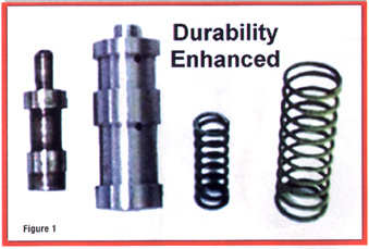
Boost valve and bushing wear occurs often. Some of the high performance valve body kits also include a replacement boost valve assembly (figure 1). These redesigned valves are modified for durability, and in general, an 0.500" land size valve with the correct porting makes a huge difference in terms of pressure control. However--and this is really important--a larger diameter boost valve won't make up for a worn pump assembly, nor will it compensate for a faulty electronic control system component.
Figure 1
And don't forget, an input device, such as the TPS, MAP or MAF, can also cause pressure rise control problems, causing a degraded or slow signal that lags well behind throttle opening.
The Science of Friction Material Composition
With the auto manufacturers' goal of better and longer lasting transmissions, a lot of emphasis has been placed on friction material composition and design. In recent years, the demand has greatly increased for scientifically advanced friction paper composition, saturation and bonding processes. This is important since many electronic transmissions, such as the Chrysler A-604, cut back line pressure when the unit is in third and fourth. To meet these new demands, a new era of friction materials, appropriately termed "high energy," have been sweeping the industry with outstanding results.
In addition, some of the same manufacturers of friction materials that supply the OEMs have been developing unique products for high performance and racing enthusiasts. Through intense, sophisticated research, these manufacturers have invested thousands of hours into developing and testing these newer high energy materials. If you haven't used the 4L60/4L60-E series 2-4 band with high energy friction material, you're missing out on a terrific product that will last forever-and-a-day ... barring external failures. The friction material responds beautifully, and you don't have to make a lot of calibration changes to achieve the responsiveness you want.
Of course, these outstanding results haven't come cheaply. A lot of money has been invested to develop these products, so don't expect performance and long-term durability at bargain basement prices. What specifically is available? Contact your parts supplier and inquire about the many different types of friction materials from both OEM and aftermarket sources. In most cases your supplier can put you in contact with the manufacturers' technical representatives, who can answer any questions you may have.
Specific Durability Concerns
With a truly high performance application such as a big block or high revving small block Camaro with a low axle ratio, it was possible to give the customer exactly what he wanted: A manual or automatic 1-2 shift that would chirp the tires. By installing the Corvette second piston or one of the super servo pistons (figure 2), the reaction sun shell comes to a sudden halt when the 2-4 band stops the reverse input clutch housing. The result is a spike overload that shears the reaction sun shell (figure 3). Stopping the reaction sun shell that quickly is risky to begin with; but there are some precautions and modifications that reduce the reaction sun shell failure.
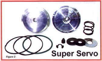
Figure 2
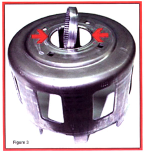
Figure 3
Check the input sprag carefully. A slipping input sprag can cause reaction sun shell failure, as well as a number of other operating problems.
Index the sun shell and reverse input clutch housing: During transmission disassembly, remove the pump and 2-4 band. Before you grab the input shaft and withdraw the top components, take a 90� scribe and mark the matched lugs in one spot. Essentially you want to be able to assemble the transmission and place the reverse input clutch housing lugs back into the matching lugs of the reaction sun shell, just as it was before the top section of the transmission was disassembled (figure 4). Here's why:
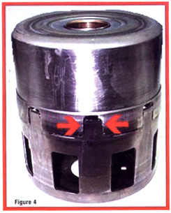
Figure 4
During the initial run-in, when the components are new, a wear pattern develops which places the contact load on all the lugged areas equally. When you assemble the transmission, if the lugged areas aren't put back in the same position they were in before disassembly, the wear pattern is disturbed and the load is now placed on one or two of the reaction sun shell lugs.
What can you do if the components weren't indexed before disassembly, or one or both of the components have to be replaced? Install the reaction sun gear into the reaction sun shell and secure it in a vise, being careful you don't damage the reaction sun gear teeth. Be sure it's tight and secure.
Next, position the reverse input clutch housing lugs over the reaction sun shell lugs and rock the drum back and forth. Lift the housing, rotate it to the next lugged spot and rock it back and forth again. Lift, rotate, and rock it back and forth until you find the one spot where the drum can rock back and forth an equal distance. Once you are satisfied with the lug indexing, use a bright colored marker and mark the two components. Then, when you install them into the transmission assembly, simply align the index marks.
The reaction sun shell and the reaction sun gear splined area could have been made stronger with heavier material and heat treated, like the revised THM 2004R series reaction sun shell. While you can't change the material structure at the bench, you can strengthen the original material. Here's how:
Whether you are going to use a new reaction sun shell or the original one, clean it thoroughly. There can't be any traces of oil, antirust agents, cleaning soap, etc. on the material. Get a styrofoam cooler with a lid, like the one you bring to the beach to keep your favorite soft drinks cold.
Cut a length of mechanic's wire, and secure one end to the reaction sun shell and leave about twelve inches of the other end extending out of the container. Place the reaction sun shell in the container and drive to your nearest convenience store that sells dry ice. As the dry ice is being placed in the container, shake the container to distribute the dry ice evenly until the reaction sun shell is completely covered. Bend the mechanics wire into the container and install the lid.
The lid must be kept closed and the reaction sun shell must not be disturbed for about twenty four hours. After 24 hours are up, remove the lid, grab the mechanics wire, and carefully remove the sun shell. Now place the sun shell gently onto a thick blanket where it can remain undisturbed, and let the it warm slowly to room temperature.
Never use heat lamps or any other heat source to accelerate the warm up time. It's also important not to handle the reaction sun shell roughly, which is why you need to use a thick blanket. Once the sun shell has warmed to room temperature, you can use a rag to wipe up any moisture or minor rust scale that has formed.
Warning: Dispose of the dry ice responsibly. If handled, dry ice can cause serious skin burns. Avoid breathing the vapor from the dry ice, which can also be harmful.
You can also use the dry ice hardening method on differential pinions (figure 5), for vehicles that experience premature yoke spline wear, resulting in a clicking sound like a failed universal joint.
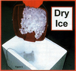
Figure 5
Finally, the Torrington bearing that rests on the input housing selective thrust spacer is prone to failure even in ordinary, light duty applications. For better service, replace this bearing during every rebuild with the bearing from on top of the AOD forward clutch hub. Ford's part number for this bea ring is E0AZ-7F231-A. Of course, setting and maintaining minimum end clearance significantly reduces the impact on all thrust bearings.
Thanks to the many readers who contacted us on our last GEARS article, covering Ford's E4OD. Your comments are most appreciated and we're delighted you enjoyed the article. Never lose sight of your goal: fix it right the first time, every time. You'll be glad you did.
Electronic control components are often reused when they really should be replaced, mostly because technicians can't "see" the wear. It's easy to see wear on a band, friction plate, bushing, planetary etc.; but wear isn't as easy to see on a pressure control solenoid or similar device.
![]()