
by Stevie Lavallee,
TEST Technical Department
Ford's EEC-IV Self Test System: Theory of Operation
 Some technicians have difficulty understanding how the Ford EEC-IV self test system operates. When compared to the diagnostics built into most other vehicles, Ford's system is unique: It can perform a host of checks during self test initialization, as evident by the clicking and clacking of various output devices, such as the electric fuel pump, shift solenoids, electric fans, etc. Once you understand how the self test system is designed, you may agree that this is one of the most comprehensive systems on the road today, and isn't merely a "code display reporter."
The Ford self test system can be separated into two main categories: Continuous Monitor, in which the computer monitors the system for faults during normal operation, and On-Demand testing, in which certain tests can be performed at the request of the service technician. As you'll see, the self test system isn't looking for faults and supplying data that's only related to the electronically-controlled transmission or transaxle. You'll see that the testing sequences are looking for faults and supplying data for the transmission, engine and emission systems.
This is the primary reason why the term powertrain should become a part of your everyday vocabulary when working on electronically-controlled vehicles, even for shops that work only on transmissions. As an example of electronic integration between engine and transmission, think of the Throttle Position Sensor
(TPS). The TPS primarily supplies an engine load input to the computer, by providing an analog voltage signal that varies with throttle opening. This varying voltage signal controls shift scheduling,
TCC, and pressure rise control for an electrically-controlled transmission or transaxle. The same TPS signal also controls engine functions such as fuel enrichment and spark control. A problem withthe TPS could cause an engine performance or driveability problem as well as a transmission problem. Remember... think powertrain!
Continuous Monitor
During normal operation, the computer will monitor various inputs and store this information in KAM (Keep Alive Memory) if it detects an error. The sensors are monitored for shorts and opens and will only set a Diagnostic Trouble Code (DTC) if they go out of normal operating range. The computer must see the sensor out of normal operating range for a certain period of time, or a certain number of times during a given time period. The computer does this so it won't set DTCs for sensors that are actually working properly.
Fault codes, once placed in the computer's KAM, will remain there until 40 engine warmup cycles have passed and the error hasn't been detected again. Continuous Memory DTCs can be retrieved easily using one of the scan tools during the KOEO portion of the On-Demand self test.
On-Demand Testing: Key On, Engine Off (KOEO)
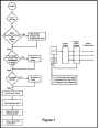 The computer performs the KOEO self test at the request of the technician using a scan tool. During the KOEO self test, the computer runs through a series of checks
(figure 1). The first check is a limited test of the computer's ability to read and write various memories. The next check is for the input circuits, in which the computer checks for inputs to be within a preset range for the KOEO self test.
The computer performs the KOEO self test at the request of the technician using a scan tool. During the KOEO self test, the computer runs through a series of checks
(figure 1). The first check is a limited test of the computer's ability to read and write various memories. The next check is for the input circuits, in which the computer checks for inputs to be within a preset range for the KOEO self test.
Unlike Continuous Monitor, the computer will not only set codes for a shorted or open sensor but also a sensor that's out of range, such as a Throttle Position Sensor that doesn't indicate closed throttle voltage. There are three main categories of DTCs that can be set for analog sensors, such as the TPS:
1. Input too high, indicating a voltage out of normal operating range, very close to reference voltage (VREF).
2. Input too low, indicating that the sensor is out of normal operating range, very close to zero volts.
3. Sensor out of range, which indicates that the sensor is neither completely open nor completely shorted, but is not in range for the KOEO self test strategy.
Testing the Output Circuits
The last test performed during the KOEO self test checks the computer's output circuits. The computer does this by briefly turning on and off specific actuators, and monitoring the voltage on the Voltage Sense Network
(figure 1). The computer energizes the actuator by closing the circuit to ground through the output driver, and looks for a voltage change. This test accounts for some of the clicking and clacking noises you hear during the self test initialization. If the computer doesn't detect this voltage change, it sends an error code for that output circuit.
When a diagnostic routine indicates an actuator is faulty, you can determine whether the computer is sending the signal to the actuator by monitoring the circuit with a digital multimeter during the self test. Simply look for the voltage change on the actuator's circuit. This procedure reduces the incidence of needlessly replacing the computer for a suspected fault.
Sending the Codes
At this time, the computer sends service codes (figure
1). The first set of service codes are sent in the following sequence:
1. Hard Faults or any codes that have been set during the KOEO self test.
2. Separator Code which is defined as Code 10.
3. Memory (History) Codes placed into the KAM circuit during Continuous Monitor.
The key points to remember about KOEO hard fault codes are that they are electrical faults within the EEC-IV system and most codes are caused by a specific circuit. Memory codes are stored from faults (Electrical or mechanical) that were set during normal operation.
On-Demand Test: Key On, Engine Running (KOER)
 The KOER portion of the On-Demand self test is a dynamic test of the computer's ability to control the various sub-systems, such as air/fuel ratio,
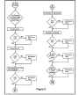
EGR, and idle speed control. The vehicle must be warmed up by running the engine at 2000 RPM for two minutes, or until the upper radiator hose is hot and pressurized and the Exhaust Gas Oxygen (EGO) sensor has reached operating temperature. Upon starting the KOER self test, the following tests will take place
(figures 2 and
The KOER portion of the On-Demand self test is a dynamic test of the computer's ability to control the various sub-systems, such as air/fuel ratio,
EGR, and idle speed control. The vehicle must be warmed up by running the engine at 2000 RPM for two minutes, or until the upper radiator hose is hot and pressurized and the Exhaust Gas Oxygen (EGO) sensor has reached operating temperature. Upon starting the KOER self test, the following tests will take place
(figures 2 and 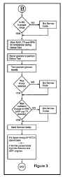 3).
3).
1. Sensor Test; the computer checks the sensor values to make sure they're within the calibrated ranges.
2. Fuel Test; the computer tests its ability to control the air/fuel ratio, by decreasing fuel injector on-time and watching for the EGO sensor to indicate a lean condition. The computer then increases the fuel injector on-time and looks for a rich signal from the EGO sensor.
3. Thermactor Air Test; the computer ramps fuel slightly rich and diverts air upstream. The EGO sensor should signal a lean mixture because of the excess oxygen in the exhaust manifolds. The air is then sent downstream, and the EGO sensor should indicate rich. The diverter valve then switches Thermactor air upstream, and the EGO sensor should remain rich.
4. EGR Test; First the computer looks at the EGR valve position sensor or pressure feedback EGR sensor to see if the sensor is within the proper range. The computer then starts opening the EGR control solenoid, which applies vacuum to the EGR valve. The computer watches the EGR sensor for an indication of EGR valve opening and closing, while watching for a slight RPM drop or a signal from the EGR pressure feedback sensor, indicating actual EGR flow through the valve.
5. ISC Test; (Figure 3) The computer tests its ability to control idle RPM by activating the idle speed control motor on CFI (Central Fuel Injection) engines or the idle speed control bypass air valve on PFI (Port Fuel Injection) engines, to see if it has the ability to control idle. This includes curb idle and a certain calibrated RPM above hot curb idle.
6. Goose Test; Now the computer begins a sequence of steps on some Ford vehicles to prepare and run the Goose Test. First it stores RPM, MAP, and TPS readings in Random Access Memory (RAM). It then sends an output pulse on the Self Test Output line
(STO). When the
scan tool indicates it, you're supposed to goose the throttle (a brief wide-open throttle). During this test the computer checks for engine knock through the Knock Sensor, and looks for sufficient change in RPM, MAP and TPS readings. The computer then sends any service codes set during the On-Demand KOER self test.
KOEO Wiggle Test
During a KOEO Wiggle Test, you wiggle and tap on certain sensors and harnesses while the computer looks for faults in certain sensor circuits, and signals if a fault occurs. During this test, the computer will store a fault code and will signal as soon as it detects a fault on a sensor line. This is why the Wiggle Test is great for finding intermittents on sensor lines. In some cases this test is also used as a computer input check during pinpoint testing. You can purposely create a short or open in a sensor line and see if the computer reacts by setting a DTC and signaling the STO. This would indicate that the computer input circuits are operating properly for that particular sensor.
KOER Wiggle Test
The KOER Wiggle Test is very similar to the KOEO Wiggle Test in that, once entered, it will notify you as soon as a fault occurs on one of the sensor lines being monitored. This test is particularity useful while road testing for intermittent problems or trying to reset memory codes that have previously occurred.
All you need to do is get into the vehicle with the scan tool, program the scan tool for the test, and then road test the vehicle. As soon as a fault occurs, the scan tool will beep or flash an indicating lamp, depending on which scan tool you're using. If a fault does occur, you can pull over to the side of the road and perform a KOEO self test to retrieve the fault code from memory. (Are you now beginning to understand and appreciate just how comprehensive the EEC-IV self test system really is?)
Data Stream Selection and Display
Data stream display is available on many of the Ford EEC-IV systems. The individual lines of data are often referred to as Parameter Identification Data (PID) lines.
The data or PID lines available for viewing will vary from vehicle to vehicle. On some vehicles there may be 10-12 PID lines available; other models can provide as many as 40+ PID lines. It's far easier and faster to diagnose faults with these newer systems that can transmit a data stream. Prior to these systems, you'd have to use a breakout box or backprobe circuits, which made testing much more time consuming. But now, with the advent of EEC-IV data stream display, it's a walk in the park.
Computer Default and Alternate Strategy
Although not considered part of the EEC-IV self test system strategy, there are two modes of computer operation that you should be aware of.
1. Failure Mode Effects Management (FMEM): This is an alternate system strategy that differs from the normal calibration strategy and initializes when a sensor input appears to be out of its normal operating parameters. The computer will use a fixed, in-limit sensor value and will continue to monitor the faulty sensor input. In many instances when FMEM initializes, the computer will look for the next relative sensor in-line and use that signal in place of the faulty signal. For example, on AX4S equipped vehicles, if the Vehicle Speed Sensor (VSS) signal should fail, the computer will substitute the Turbine Speed Sensor (TSS) signal, interpret its information, and use it in place of the VSS signal. In most AX4S vehicle applications, when the VSS circuit fails, FMEM elevates EPC pressure, causing firm engagements and shifts and usually no fourth or no TCC apply.
2. Hardware Limited Operation Strategy (HLOS): This alternate system strategy is initialized when the system fault is too extreme for FMEM to handle. In this mode, all internal computer software strategy stops and the computer operates on hardware control only. The strategy for this mode has minimal calibration and is used only to allow the vehicle to operate until it can be serviced.
As you can see, the Ford EEC-IV self test system is far more than just another system for retrieving codes. With EEC-IV, Ford has put together a complete self-diagnostic system, in which the computer works with you to help you diagnose nearly every level of system control and operation.
I would also like to express special thanks to the Hickok Automotive Training Group for contributing information to this article. The Hickok Electrical Instrument Company is the firm that develops and manufactures the Rotunda brand of test instruments for Ford Motor Company such as the New Generation Star
(NGS) Tester and the Transmission Tester. The NGS is a fully featured, bi-directional Scan Tool and the Transmission Tester is a hand held unit that allows transmission output command control independent of the vehicle's on-board electronic system. Thank you for your attention and the TEST Technical Department wishes you the very best for your continued success.
