 by Steve Garrett

 by Steve Garrett
The Allison LCT 1000, Part 2
In the last issue of GEARS we reviewed the general construction of the new Allison 5-speed transmission. In this issue we'll examine the mechanical and hydraulic operation of this unit.
The LCT 1000 uses five multiple disc clutches, numbered C1, C2, C3, C4 and C5. They are numbered in sequence, starting with C1, which is in the front of the case. C1 mounts inside the housing that also supports the C2 clutch. Both clutches are designed to connect to the input shaft. By applying and releasing either C1 or C2, the unit can transfer power to the planetaries. C3, C4 and C5 connect a planetary member to the case. By varying which drive clutch and which holding clutch is applied, the LCT 1000 can provide the various gear ratios.
The planetary gear sets are numbered P1, P2 and P3. Each planetary consists of a sun gear, internal ring gear, and a carrier assembly. Like many other transmissions, the LCT 1000 planetaries share components between one another. For example, the P3 ring gear is splined to the transmission output shaft, while the other planetaries connect to each other, as well as to the clutch assemblies.
Power flow through the transmission starts at the input shaft, which connects to the C1/C2 clutch housing. Here's how the clutches interact with the various components:
C1: Connects the input shaft to the transmission mainshaft. The mainshaft connects to the P2 and P3 sun gears. This drives the P2 and P3 planetaries at turbine shaft speed.
C2: Connects the input shaft to the P2 carrier and the P3 ring gear. This drives the P2 carrier and the P3 ring gear at turbine shaft speed.
C3: Locks the P1 ring gear to the case.
C4: Locks the P1 carrier and the P2 ring gear to the case.
C5: Locks the P2 carrier and the P3 ring gear to the case.

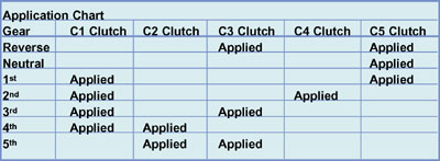
As you can see from the clutch application chart, this unit requires two clutches to apply for the vehicle to move forward or backward. Which two clutches determines the direction the vehicle will move, and which gear the transmission is in. Unlike most other transmissions, the same clutches apply for both manual and OD ranges. Manual ranges only limit the number of upshifts or downshifts the transmission can command.
Powerflow
1st Gear: The C1 and C5 clutches apply. The C1 clutch drives the P3 sun gear at input shaft speed. The C5 clutch prevents the P3 ring gear from rotating as the P2 carrier attempts to turn it. This means the P2 planetary turns, but it isn't transmitting power. The C1 clutch also rotates the P3 sun gear, which forces the P3 carrier to walk around the stationary P3 ring gear, producing maximum
underdrive. The P3 carrier connects to the output shaft, which rotates at a 3.10:1 ratio. This transmits power through only the rear planetary gear set
(figure 1).
2nd Gear: The C1 and C4 clutches apply. The C1 clutch drives the P1, P2 and P3 sun gears while the C4 clutch holds the P2 ring gear stationary. The P1 planetary rotates, but isn't transmitting power. The P2 sun gear rotates the P2 carrier, forcing it to walk around the stationary P2 ring gear. As the P2 carrier rotates, it forces the P3 ring gear to rotate, both at maximum underdrive. As the P3 ring gear rotates, it forces the P3 carrier to walk around the moving P3 ring gear to provide a 1.81:1 ratio (figure 2).
3rd Gear: The C1 and C3 clutches apply. The C1 clutch drives the P1, P2 and P3 sun gears, and the C3 clutch locks the P1 ring gear to the case. The P1 sun gear then drives the P1 carrier and P2 ring gear. The rotation of the P2 sun gear forces the P2 carrier and P3 ring gear to rotate at a reduced speed. The P3 sun gear then forces the P3 carrier to walk around the P3 ring gear, which is already in motion. Since the P3 ring gear is rotating, the gear ratio decreases to a 1.41:1 ratio (figure 3).
4th Gear: The C1 and C2 clutches apply. The C1 clutch drives the P1, P2 and P3 sun gears, and the C2 clutch drives the P2 carrier and P3 ring gear at turbine speed. Since the planetary sun gears, P2 carrier, and P3 ring gear are all turning in the same direction and at turbine speed, the P3 carrier pinions rotate in the same direction and speed as the input shaft, resulting in a 1:1 ratio (figure 4).
5th Gear: To provide overdrive, the LCT 1000 applies the C3 and C2 clutches. The C2 clutch drives the P1 sun gear and P2 carrier at maximum underdrive, while the C3 clutch holds the P1 ring gear stationary. With power flowing into the P2 carrier, the P2 and P3 sun gears rotate at an overdrive ratio. With the P3 ring gear rotating at input shaft speed and the P2 and P3 sun gears rotating faster than that, the P3 carrier is driven at a 0.71:1 ratio (figure 5).
Reverse: The C3 and C5 clutches apply. The input shaft drives the P1 sun gear. The C3 clutch holds the P1 ring gear, forcing the P1 carrier and P2 ring gear to rotate in an underdrive ratio. The C5 clutch holds the P3 ring gear and P2 carrier stationary. This rotates the P2 sun gear in reverse, while the P1 carrier and P2 ring gear rotate forward. The P3 carrier walks around the stationary P3 ring gear in reverse at a 4.49:1 ratio (figure 6).
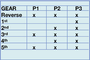
Here's a summary of the power flow through the planetaries to assist with noise diagnosis:

As you can see, the power flow through this unit is pretty complex. Rest assured that somewhere, an engineer spent countless sleepless nights figuring out how to make all of this work.