The Allison LCT 1000, Part 3
by Steve Garrett
The Allison LCT 1000, Part 3
by Steve Garrett
In our last meeting we reviewed the general construction of the new Allison 5 speed transmission. In this segment we will examine the hydraulic operation of this unit.
Remember how simple the hydraulic systems became when electronic control systems were introduced? Fewer valves, easier circuits to follow and a system that most people would say was easier to diagnose and repair. Well the hydraulic system used on the LCT 1000 may be a wakeup call for all of use whom were lulled to sleep by how simple the systems had become.
The LCT 1000 valve body assembly houses 14 valves and 6 solenoids. Sounds pretty simply doesn't it? Well it would be if valves and the solenoids operated like the ones in our conventional electronic transmissions. Lets take some time and explore how this thing really works!
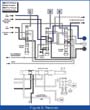
The valve body assembly consists of two halves, the "shift valve body" and the "Main control valve body." The assembly is bolted to the case as with any conventional rear drive transmission (Figure 1).
Pressure Regulation
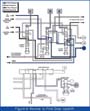
In a typical GM electronic transmission, one would expect to see a pressure control solenoid (PCS) which would be used to control line pressure boost. The LCT 1000 does not use a PCS. Instead it uses a conventional PR valve (Main Regulator Valve) to control line pressure to a "fixed amount" (Figure 2). This means the days of seeing line pressure respond like other transmissions are over when your working with this unit.
Line pressure is strictly determined by pump volume and the position of the Main Regulator Valve!!!! Unlike other transmissions, Mainline pressure is not fed directly to most of the clutches to control their apply.
The Main Regulator Valve position is controlled by the amount of bias pressure on the top of the valve verses the spring pressure at the bottom of the valve. As the valve is forced down in its bore the main line pressure is allowed to "exhaust into the inlet" of the pump, lowering system pressure. When the valve moves up in its bore main oil pressure is fed into the "overage" passage which feeds the cooler when TCC is applied and the converter when the TCC is released.
The other passages at the Main regulator valve also provide some specific functions. The TCC signal passage is used to " cut back" line pressure when TCC is applied. This function reduces the load on the pump/engine when the TCC is applied as lower pump volume is required when the TCC is applied. This is due to the fact that the converter does not require high volumes of fluid when the TCC is applied.
The overdrive knockdown passage is not currently used, but it was designed so that trim solenoid "B" pressure could be used to lower line pressure after the unit had shifted to 5th gear.
Two more valves are used to help regulate the system pressure. The valves are referred to as the "Control Main" and the "Control Main Relief" valves (Figure 3).
The Control Main valve function is to reregulate mainline oil pressure. The pressure coming out of the control main valve is called control main pressure. Control Main pressure is the pressure which is used to feed the shift valves, manual valve and the PSA. Its operation is quite similar to the main regulator valve as it is controlled by bias pressure verses spring pressure on the opposite end of the valve.
The Control Main Relief valve is simply used to exhaust pressure if it were to become too high.
Manual Valve
The manual valve also operates a little different from the conventional transmission you have been used to dealing with. The manual valve can move into just 3 different positions: Drive, Neutral and Reverse (Figure 4). When a range other than one of the above has been selected by the driver the manual valve will still be in only one of the 3 positions available. In other words, Park and neutral result in the same hydraulic operation. Manual forward ranges result in the same hydraulic operation as D range does.
This means the manual valve does not control the hydraulic system operation when the customer selects a manual range. The TCM controls all the manual range operations in this unit. All forward ranges are identical hydraulically and Park/Neutral is identical hydraulically (Figure 4).
If the customer selects either reverse, or neutral/park range the manual valve will exhaust the C1 and C2 clutches. When the customer selects reverse range the manual valve will direct fluid pressure through the "D" shift valve to apply the C5 clutch. The C3 clutch is applied by pressure from the "A" trim solenoid, which also travels through the "D" shift valve (Figure 5).
When a forward gear range is selected the manual valve provides oil pressure for the C1 clutch. The C5 clutch is fed from the "A" trim solenoid, which is fed through the "D" shift valve. Figure 6
Trim Solenoids And Valves
The LCT 1000 uses 2 trim solenoids to control shift feel (Figure 7). Unlike other transmissions, line pressure is not used to initially apply the clutches.
As mentioned above, 2 solenoids are used, trim solenoid "A" and trim solenoid "B." Both solenoids are PWM controlled and are controlled by the TCM. Trim solenoid "A" is "normally closed" while trim solenoid "B" is "normally open.
"Control Main Pressure" is fed to both solenoids to control the position of the solenoid trim valves. Main line pressure is fed to the trim valves. Mainline pressure is then reregulated by the trim solenoid and valve. This reregulated pressure (Trim pressure) becomes the supply pressure for the clutches. To control the trim pressure the TCM controls/cycles the solenoid on/off by varying the duty cycle command (PWM) at a fixed frequency of 1000 HZ. The amount of time the solenoid is energized determines the position of the trim valves. As the PWM signal changes, the amount of pressure applied to the top of the trim valve also changes.
Increasing the amount of pressure on the top of the trim valve will result in an increase in feed pressure/volume to the shift valve and clutch. Decreasing the amount of pressure available to the top of the trim valve will result in reduced the pressure feed to the clutches/shift valves. The duty cycle command at the solenoid determines the amount of pressure available at the top of the trim valve. As you can see, shift feel is really function of the trim solenoid and trim valve position.
Accumulators are located parallel in the trim solenoid Control Main circuits. The accumulators stabilize the pressure to limit the amount of pressure fluctuations at the trim valves (Figure 7).
Shift Solenoids/Shift Valves
Three shift valves and solenoids are used in the LCT 1000. Each shift valve is controlled by an individual solenoid. The shift solenoids and shift valves designated as "C," "D" and "E." The shift valves control the trim pressure and main line pressure, which is fed to the C3, C4 and C5 clutches. All the solenoids are "normally open" which means they must be energized to close the solenoid exhaust. The shift solenoids are ON/OFF style assemblies (Figure 8).
The shift valves are used to control the direction of flow for Main line, Control Main and Trim pressures within the valve body. One of the most unique features of the LCT 1000 is how the shift valve train works. Typically the shift solenoid is turned either on or off to position the shift valve so trim pressure can flow through the valve and to the clutch or from the clutch to exhaust. Trim pressure then regulates the clutch apply by controlling the pressure and volume available to feed the clutch.
Once the shift has occurred, the TCM will reposition on of the shift solenoids and its accompanying shift valve. This action stages the shift valves into the proper position for the next shift. This feature will definitely take some getting used too. It's confusing enough to remember solenoid sequences for a conventional electronic transmission. This feature really makes one think!
As you can see, this transmission will be quite a challenge. Well that's about all the time we have for now, see you next time.