Taming Some Tough Transfer Case Problems
by Mike Weinberg,
President of Rockland Standard Gear Inc.
Taming Some Tough Transfer Case Problems
by Mike Weinberg,
President of Rockland Standard Gear Inc.
If you work on 4-wheel drive trucks, then you've seen the Borg Warner 1356 and the New Process 241 transfer cases. These are two very common units that have some difficult problems to solve. In the following pages, I will discuss some of these problems and their associated fixes. For those of you planning to attend this year's Expo in Rhode Island, you'll get even more fixes for some standard transmission problems during my Stick Tricks seminar.
Let's start with the Borg Warner 1356 and some common planet problems. Late design planets have a bronze thrust washer between the back of the input gear (sun gear) and the back of the planetary carrier case (figure 1). These washers wear out due to thrust loads creating excessive endplay in the carrier. The carrier cannot be disassembled and must be replaced as an assembly. The clearance between the input gear ( sun gear) and the back of the planet carrier should not exceed 60/1000 of an inch. Early design planets were produced without the thrust washer, but still have wear problems causing excessive endplay and disengagement of the transfer case. Clearance should not exceed 60/1000 of an inch.
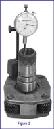
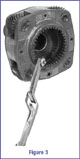
You can measure the input clearance as shown in figure 2 with a dial indicator. Zero the indicator with the input resting in the planet case. Pull up on the input gently and read the indicated amount of travel. The same measurement can be made with a feeler gauge. Place the gauge between the bottom of the input and the planetary case to measure the clearance (figure 3). Either method of measurement will work with early or late design planets.
Another common problem with the 1356 is case wear. It is not unusual for the oil pump-retaining bracket to damage the case. Figure 4 shows that this particular case has a notch at least half way through the aluminum boss.
There are two ways to fix this problem without replacing the case: one method is to bend the bracket to relocate it to a fresh spot on the case. The second is to rivet or weld a small foot on the end of the bracket that is the same width as the slot in the case, which will prevent further wear. If the bracket is allowed to eat through the case, the oil pump will spin on the shaft; tearing out the feed line and the unit will self-destruct due to lack of pressurized lube.
Manually shifted units usually exhibit wear on the selector shaft in two areas (figure 5). Shaft wear in any form will make the unit disengage or have very sloppy shifting. The star shaped end of the shaft where it mates with the shift cam is also prone to wear. Borg Warner released an updated shift cam with an Allen screw to tighten up the fit and retain the manual lever. Look at the section of the manual lever that rides in the case, which is also subject to wear from dirt and two dissimilar metals in close contact.
Always inspect the bore of the case for excessive wear. Figure 6 shows the bore is worn over size and will no longer hold the selector shaft in position. The only way to fix this is to do some machining and sleeve the bore, or to replace the case altogether.
Another common complaint of the 1356 is that it will sometimes exhibit a driveline thump or clunk on take off. Many shops have spent considerable time balancing drive shafts, replacing u-joints, mounts, etc. without success. The problem lies inside the transfer case itself. A careful examination of the rear output shaft will reveal excessive end play between the shaft and the rear bearing, and between the rear bearing and the extension housing. You should use shims to take up the endplay between the output shaft and the rear bearing retaining snap ring (figure 7). You can use Chrysler part #00015128 for a shim kit that will enable you to take up the endplay between the bearing and the output shaft snap ring.
Figure 8 shows how to take up slack between the rear output bearing and the extension housing using Spicer shim kit 701121X which fits the outside of the bearing and prevents it from traveling rearward against the extension housing. This shim is designed for a pinion shim in a Dana 35 rear end and fits perfectly. By using these methods to fix the endplay of the output shaft you will solve many problems that have baffled dealers and other repair shops for years.
NP 241 Transfer Case
The NP 241 Transfer Case (Figures 9a, 9b) has been used in General Motors since 1987, and Dodge trucks from 1988. This transfer case features helical gears in the low range planetary for quieter operation. This improved the drive comfort during low range operation, but can create several areas of failure that must be considered when rebuilding one of these units.
Figure 10a shows the complete planet assembly. Any time you are working on one of these units you must disassemble the planet and inspect it internally for damage. There are many points of wear in the input gear, which forms the sun gear of the planet.
In Figure 10b, the sun gear has been disassembled and the top steel washer, which is being held in a clamp, is clearly visible. You will notice that the washer is no longer flat, but curved much like a Belleville spring. This happens because helical cut gears want to "walk" away from the thrust load of the gears bending the washer. Oversize tires, lift kits, and high numerical ratio gear sets all add to this problem.
Figure 11 shows heavy step wear on the internal teeth of the input that engage the range sleeve. The teeth are originally cut with a back taper angle to hold the range sleeve in place under load. When this angle wears out, the thrust load forces the range sleeve out of engagement, resulting in further damage to the input, range sleeve, and the fork.
Speaking of the fork, figure 12 shows clearly, the damage to the fork and range sleeve. The engagement teeth on the range sleeve show the same advanced step wear found on the input, and the thrust load generated on the fork wipes out the lubrication between the fork and the sleeve causing rapid failure. If you have a fork that shows this wear without any damage to the range sleeve, low lube levels probably cause it. Whenever you are replacing a damaged fork, replace the range sleeve as well. The fork groove on the range sleeve is finished with a specific micro finish. When the fork wears, it will damage that surface finish on the sleeve. If you only replace the fork, the rough surface of the sleeve groove will quickly damage a new fork creating a probable come back situation.
In figure 13 we see that the internal splines of the input shaft are badly worn. This type of damage causes clunks on engagement of the transmission and during throttle applications and coast conditions. If you have a complaint of driveline clunks, check this spline area. Many universal joints are replaced only to have the same problem due to worn splines.
A very common failure of this unit is the snap ring that retains the main shaft to the rear case bearing. When the snap ring breaks or pops off due to thrust loads, it permits the shaft to move forward. This, in turn, moves the shaft journal out of the oil pump seal area causing a loss of pressurized lube. The shaft and the gears in figure 14 have obvious metal transfer from lack of lubrication and must be replaced. Shown at the right is the stock snap ring which is of the open end type. Any time you rebuild one of these units discard the factory snap ring and replace it with a circlip, which is shown nearer the gear in figure 14. This circlip is from the Borg Warner 1356 transfer case and is readily available. The "eyelet" type of snap ring we recommended is capable of handling much greater thrust loads and has proven to solve this problem.
In figure 15 we see extensive synchronizer damage. The points on the engagement teeth on the sprocket and the slider show heavy damage. The synchro ring is badly worn. The output shaft snap ring breaking or moving off and letting the shaft move out from under the synchronizer causes this failure
Figure 16 shows a classic example of synchro ring failure. The synchro ring at the left is badly worn and sits down too far on the cone. The ring at the right is new and shows proper ride height on the cone. It is common to measure the ride height from the bottom of the synchro ring to the top of the engagement teeth and compare with the factory specification. This is known as Synchronizer "Reseve."
A superior method is to clean and dry the cone of the gear thoroughly, paint the cone with Prussian blue (die makers layout blue) or a good felt marker. Then twist the ring onto the cone, as it would be applied in the unit. Remove the ring and check the pattern it makes on the cone. This will give you an absolute graphic picture of the ring's ability to grab the cone. This method will work on any type of synchronizer and is much more precise than just taking a ride height measurement. Synchro ring reserve measurements will not reflect any wear on the cone of the gear and it is impossible for you to measure a tapered surface accurately.
I'll be covering more common complaints and fixes on these units and many more in my Stick Tricks seminar at this year's Expo, TRANSMISSIONS 2001 in Providence Rhode Island--I look forward to seeing you there.