![]()
Often times I
receive calls from Transmission Surgery
Centers in reference to neurological
(electrical) testing. In response
to these calls I am finding it more and
more important to make these electrical
tests quickly and accurately, but still be
complete enough so as to let the next of
kin (auto owner) know where to go for
their repair decisions. In this issue of
Doctor, Doctor we’ll cover some basic
tests that will help you, the Doctor, get
the answers you need, in order to resolve
transmission electrical problems. We’ll begin with basic tests. In
articles to follow we will cover other,
more sophisticated tests. As we go
along, you will see just how easy these
tests are. Ok lets get started. First we’ll
check the power and ground circuits! The Battery The battery is used only to start the
vehicle and maintain a memory voltage for
the controllers when the vehicle is turned
off. The alternator is used to supply
voltage to all of the power systems, and
to keep the battery charged so it can
start the vehicle. We’ll cover the alternator
later. All electrical tests must start at the
heart of the system, the battery (Figure
1). In order for the brain to function
correctly it must have the proper electrical
input from the battery. If there’s a
problem with the battery, even basic
tests, like scanning the vehicle for trouble
codes can be misleading. Caution: Before you test the battery,
view the safety items in figure two.
Batteries can explode under certain
conditions.
1: Never bring any source of combustion
near the battery (including cigarettes).
The gasses being emitted are hydrogen
and oxygen: an explosive and an
accelerant. Adding a spark to this mix
can easily cause an explosion. 2: Never attempt to jump or charge a
battery that is cracked, gassing excessively,
or been frozen. 3: Always make sure your battery charger
is turned off before connecting or
disconnecting it from the battery. 4: If the battery has removable caps,
always check the level in the battery
before attempting to jump or charge it.
If any of the cells are low, fill it to the
proper level with distilled water. 5: Always wash your hands immediately
after handling a battery, to remove any
acid residue. 6: Always wear protective eyewear when
working near a battery, to prevent
acids from splashing into your eyes. It
is always a good idea to wear protective
clothing such as an apron and
gloves. 7: Make sure there is eyewash is in the
shop just incase contact with eyes has
occurred. Always seek medical attention
if you have gotten any acid in
your eyes. 8: NEVER connect or disconnect battery
cables with the engine running. 9: When disconnecting the battery
cables always remove the negative
cable first, and reconnect it last. ALWAYS BE AS SAFE AS YOU CAN BE! If
you follow these procedures, you
shouldn’t have any problems when
servicing a battery. The first test is to check the  Electrical
Testing in the O.R.
Electrical
Testing in the O.R.
"Operating Room"... Part 1
by Randall Schroeder
Figure 2
Battery Safety
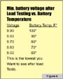
The next test is the load test. This test requires a special load-testing tool. Many tools for this purpose are available (Figure 5). Again, check the safety precautions in figure two before making this test.
One thing I’ve learned over the years is that if you don’t have these tools, many battery specialty shops will gladly work with you, as long as you work with them. Kind of like, you scratch my back and I’ll scratch yours. If they test the battery, and it needs replacement, buy the battery from them. You’ll probably find more batteries that pass the load test than do not, and as long as you’re using their batteries you can usually get the test done for free.
An alternate way to do a load test in a pinch is to disable the ignition system so the vehicle will not start. Turn on all the accessories, and crank the engine over for 15 to 20 seconds. Does the battery fall on its face, or does it recover? Figure six shows a normal rate of discharge after doing a load test. If it passes you are off to the next test.
Warning: Some cars will operate the fuel injection even with the ignition disabled. If you use the test method just mentioned, make sure the fuel injection is disabled as well. Failure to do so can result in catalytic converter damage. We want to have a blast while doing these tests, but not this kind.
The Charging System:
After doing the load test, battery voltage will be a bit low. Now start the engine and measure the charging voltage. Charging voltage will often be as high as 15 volts (figure 7). As the alternator charges the battery, the voltage will drop. A good charging system will charge at 13.2 to 13.6 volts. If the alternator is over charging, take care of it before moving to the next test. Common causes of over charging are with the regulator and diodes in the alternator. In either case, you’ll need to replace the alternator.
One side effect of diode failure is EMI or Electrical Magnetic Interference. This interference can and will fly around the engine compartment. When this happens it can interfere with things such as speed sensors, throttle position sensors, rpm sensors etc., and can affect shift timing and shift feel, because the computer (brain) can misinterpret the signals from these sensors. Here again just as in the load test, there are special testers for the alternator that not every shop will have. If you do GREAT! But if not, work out that barter deal with the electrical shop in your area.
An alternative to testing the alternator on the vehicle is to remove it from the vehicle and have it tested on an alternator machine.
Ground Checks:
This is where we can make or break all the diagnoses. Again, we are going to start the tests at the battery and work our way through the rest of the systems, so you have a full understanding of grounds. All cars use a series of power and ground leads to make them run. The ground cable at the battery is one of those things that is often over-looked, yet can cause many headaches.
Ground circuits can be summed up into three types: Battery, accessory, and sensor. Battery ground is the main ground cable that connects the negative post of the battery to the engine block (Figure 8). To test the negative battery cable, put the negative lead of your DVOM on the negative battery post and positive lead on the engine. With the ignition on, your meter should measure no more than .1 volts (figure 9). If you have more than .1 volts, check the bolt where it is connected to the engine, and repair as needed (i.e. clean the acid buildup under cable lead, tighten the bolt, etc.), or replace the cable.
Accessory grounds: These are the small wire grounds that link the ground circuit of the accessories back to the battery. Some of these grounds may be hooked to the radiator support (figure 10), fender (figure 11), frame, or to dash panels. They can be just about anywhere, but the fact is they have to complete the circuits, all the way back to the battery. Here again, there can be no voltage in the ground! And again, our threshold is .1 volts. It is very important that when checking out the circuits in an automobile that you make your tests from the battery, while the engine is running. Safety is an issue here as well. Set the parking brake and block the wheels, to help prevent any accidents from happening if the transmission were to somehow fall into gear. To test the accessory grounds you may need to make yourself a cable that will run the entire length of the vehicle you are testing. Motor homes can be fun because you need some really long cables. I have found that heavy speaker wire works the best (figure 12).
Sensor grounds: Sensor grounds, unlike battery or accessory grounds may have a little more voltage present. When I say a little more I am talking like 0.3 volt. The reason for this is that these grounds come from a control unit of some sort, and from the inside of the control unit they go to an accessory ground. And the sensor ground lead at the control unit is not always connected directly to the control unit’s ground wire. The higher voltage on the sensor ground lead does not always indicate a control unit problem. However, as with other ground circuits, the control unit’s ground must not have any voltage!
When checking the sensor ground, you must first start your test at the sensor (Figure 13). Here, just like the battery cable check, you will have the negative lead of the DVOM on the negative battery post and check the grounds with the positive lead. If sensor ground voltage is high, say, .5 volts or more, follow the ground wire through the circuit to the computer. If you have voltage anywhere in the circuit, continue checking the voltage until goes to zero. At that point you’ll know which wires are damaged, and need replacing. Now we seem to have jumped into the next stages of electrical testing: Checking out the inputs of the control systems. We’ll do that in the next issue of Doctor, Doctor.
Things to remember about battery and charging system are:
1. The battery is used only to start the vehicle and maintain a memory voltage for the controllers when the vehicle is turned off.
2. The alternator is used to supply voltage for all the power systems, and to keep the battery charged so it can start the vehicle.
With this out of the way till next time, keep those transmissions in good health!
The Doctor