![]()
Allison LCT 1000
Part 6 of 6
Welcome back! We left off last time discussing how the inputs operated for the LCT 1000. In this segment we’ll discuss how the output systems work together to control the operation of this unit, as well as the diagnostic support for this unit.
The LCT 1000 uses six solenoids to control the operation of the unit. The solenoids are attached to the valve body similar to other transmissions. Solenoids A, B and F are pulse width modulated while the C, D and E solenoids are simple on/off units. Solenoids A, C, D, E and F are normally closed, while solenoid B is normally open.
Trim Solenoids
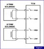
The TCM provides both power and ground to both A&B trim solenoids. The TCM supplies the ground for the solenoids (unless a fault occurs). The TCM pulses the power side of the circuit to control the amperage through the solenoid (figure 1). As the computer increases the signal duty cycle, amperage through the solenoid increases (figure 2). As with other duty cycle-controlled solenoids, the output pressure from the solenoid is proportional to the current flow through the solenoid. In addition, the higher the duty cycle the greater the solenoid magnetic field strength.
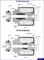
The strength of the solenoid magnetic field determines the position of the solenoid pintle (shaft), which determines the hydraulic pressure the solenoid regulates, or allows (figure 3). The LCT 1000 uses the trim solenoids to control shift feel. Unlike other transmissions, line pressure isn’t used to apply the clutches initially. As mentioned above, two solenoids are used: trim solenoid A and trim solenoid B. Mainline pressure is fed to both solenoids to control the position of the solenoid trim valves. Mainline pressure is fed to the trim valves. Mainline pressure is then re-regulated by the trim solenoid and valve. This re-regulated pressure (trim pressure) becomes the supply pressure for the clutches. To control the trim pressure, the TCM cycles the solenoid on and off by varying the duty cycle command (PWM). The amount of time the solenoid is energized determines the position of the trim valves. As the PWM signal changes, the amount of pressure applied to the top of the trim valve also changes.
Increasing the amount of pressure on the top of the trim valve increases feed pressure and volume to the shift valve and clutch. Decreasing the amount of pressure available to the top of the trim valve reduces the pressure feed to the clutches and shift valves. The duty cycle command at the solenoid determines the amount of pressure available at the top of the trim valve. As you can see, shift feel is really a function of the trim solenoid and trim valve position.
Accumulators are located parallel to the trim solenoid control main circuits. The accumulators stabilize the pressure to limit the pressure fluctuations at the trim valves.
Shift Solenoids
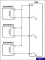
Solenoids C, D and E are used to control the transmission shifts. The TCM provides the power source for all three solenoids, which they share. To control the operation of each individual solenoid, the TCM controls the solenoid ground circuit. To turn on the solenoid, the TCM provides the ground path for solenoid current flow. To turn off the solenoid, the TCM simply removes the ground for the solenoid circuit (figure 4).
Each shift valve is controlled by an individual solenoid. The shift solenoids and shift valves are designated as C, D and E. The shift valves control the trim pressure and mainline pressure, which is fed to the C3, C4 and C5 clutches. All of the solenoids are normally open, which means they must be energized to close the solenoid exhaust.
The shift valves are used to control the direction of flow for mainline, and control main and trim pressures within the valve body. One of the most unusual features of the LCT 1000 is how the shift valve train works. Typically the shift solenoid is turned either on or off to position the shift valve, so trim pressure can flow through the valve to the clutch or from the clutch to exhaust. Trim pressure then regulates the clutch apply by controlling the pressure and volume available to feed the clutch.
Once the shift has occurred, the TCM will reposition one of the shift solenoids and its accompanying shift valve. This action stages the shift valves into the proper position for the next shift. This feature definitely takes some getting used to. It’s confusing enough to remember solenoid sequences for a conventional electronic transmission. This feature really makes you think (figure 5)!
TCC Solenoid
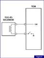
The TCC circuit in the LCT 1000 is controlled by solenoid F. Solenoid F is normally closed, and is pulse width modulated to control the TCC’s apply and release. The TCM provides the power feed to the solenoid. To control the solenoid operation, the TCM pulses the ground side of the solenoid circuit (figure 6).
Similar to other transmissions, the TCC solenoid controls the position of a valve, which controls the TCC and its hydraulic circuits. Solenoid F controls the position of the converter flow valve. As solenoid duty cycle increases, the
TCC valves open to allow the TCC to apply (figure 7). The TCC (Torque Converter Clutch) can be applied in 2 nd , 3 rd , 4 th or 5 th gears, depending on the need. In addition, TCC can be applied during deceleration, especially when the vehicle is driving downhill, to provide grade retard action. The TCC is also applied when the transmission is in neutral and the PTO is on.
Diagnosis and Testing
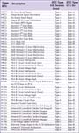
As with many other computer-controlled transmissions, the LCT 1000 has several DTCs to help you isolate the source of the possible problem. We’ve included a list of the transmission DTCs for the LCT 1000. The code type is consistent with other GM applications.
As with other applications, most DTCs will also cause the TCM to command some form of default action to occur. Remember, these trucks have both a TCM and a PCM. Many PCM DTC’s may result in transmission default actions just like transmission DTCs.
It is important to keep in mind two other bits of information when working on the LCT 1000: