 The
New Kid on the Block Can Be a Real
Troublemaker
The
New Kid on the Block Can Be a Real
TroublemakerCD4E Turbine Speed Sensor Headaches
by Mike Van Dyke
The
New Kid on the Block Can Be a Real
Troublemaker
CD4E Turbine Speed Sensor Headaches
by Mike Van Dyke
The latest design replacement CD4E turbine speed sensor (TSS) and its related problems have been the subject of many calls on the HelpLine recently. I remember one call specifically that really nailed down some of the problems related to the new design sensor. What helped was that the technician was really intent on finding the cause of this problem. The call went something like this: After getting the account number I asked him what he was working on.
"I have this í96, 626 with a CD4E transaxle we overhauled about a week-and-a-half ago. It came in with a broken drum. We went through it and replaced the drum. The original valve body was worn in the pressure regulator bore area, so we installed a new valve body and solenoid block. We also installed a new MLPS, VSS, and a new TSS, which was a new design that looked different and came with a longer mounting bolt. We donít like to reuse electrical parts because weíve seen too many problems caused by old parts.
"Now, every few days this thing comes back with the same problem, harsh upshifts and the OD light is flashing. It usually has the same codes: P0742 (TCC performance), P0733 (third gear ratio error) or P0732 (second gear ratio error)."
I asked, "When you clear the codes, will they reset on a road test?"
"Iíve driven this car home, on parts runs, all the way to kingdom come and back again, and I canít get the codes to set. But when I give it back to the customer, theyíre back within two days with the same complaint."
Itís frustrating and difficult to diagnose problems when you canít duplicate them. It doesnít help that Mazdas with CD4Es are very reluctant to give a data stream. All you have are some DTCs and an impatient customer. I started thinking about why the codes would set with the customer, but not when the technician road tested the car. The conditions must be different somehow.
I asked, "Has the customer mentioned
what the conditions were when the
overdrive light started flashing? Was it
when he was accelerating? At a cruise?
What speed? Cold? Hot?"
Trying to see if there was some way we
could duplicate the conditions. "No, he
didnít say. Maybe what Iíll do is get a
hold of the customer and see if he
recalls the conditions of how the car was
being driven." The callback afterward indicated
that some progress had been made:
"The customer says thereís a long grade on
the way to work everyday. Sometimes he
gets stuck behind a slow-moving truck.
When he pulls out into faster-moving
traffic to pass the truck, thatís when the
trouble starts." That was the keyÖ the condition. And
with that the technician was able to
duplicate the problem. But what was
causing the problem? The codes indicated there was a slip in second
gear, third gear, and at times even
excessive converter clutch slip. The upshifts were always consistent and
positive. The technician didnít detect any
slip via a "seat of the pants"
test. A pressure gauge indicated that line
pressure was consistent with throttle
opening when the codes set, ruling out
insufficient line rise. A signal
monitor indicated the transmission
upshifted and down-shifted when commanded,
and was always in the commanded
gear. At this point we suspected an input to
the PCM was more than likely the culprit,
and the one input used to calculate
converter clutch slip and gear
ratios is turbine speed. After
deliberation, the technician
decided to substitute another TSS he had
taken off of a core unit. Viola! No more problems! Now he
could wind up the rubber band real tight
on that little Mazda with no complaints
from the PCM. There were many calls after
that in which the technician was able to
duplicate the problem with highway speed
kickdowns, which made diagnosis much
easier knowing what to look for. Here are the latest observations on
this hot topic: The TSS is in a prime location to cause
trouble. The Powertrain Control Module (PCM)
calculates torque converter clutch slip by
comparing engine RPM to turbine shaft RPM.
The PCM also calculates gear ratios by
comparing turbine shaft RPM to the vehicle
speed sensor signal. The result is that a
bad TSS signal can cause both TCC
performance codes and gear ratio error
codes. A common complaint heard is the
overdrive light starts flashing after a
4Ė3 heavy throttle kickdown at highway
speeds, such as when overtaking another
vehicle. Under these conditions, a third
or second gear ratio error can set due to
the new design sensorís lower signal
output voltage at high RPM. The magnetic field of the new design
sensor from Ford (P/N XS7Z-7M101-KA) is quite a bit weaker than
the previous design (figure 1), and the
sensor has a lower signal voltage output
than the previous design (figure 2).
Additionally, the signal voltage curve
generally flattens out as turbine shaft
RPM increases (figure 3). Previous
Design Sensor New Design
Sensor Figure
2
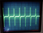
Signal pattern
at 2000 RPM New Design
Sensor Figure
3 There are a few points to consider. If
you take a closer look at the wave-forms
in figure 2, youíll see thereís a sharp
pulse upward (positive), then a sharp
pulse downward (negative), followed by a
relatively longer flat line (zero). Here is an analysis of the wave-form in
figure 5 and how the magnetic field
contributes to sensor output. This gives
you a little insight into what
Figure 1


Magnet will pick up 1.25 lb pump gears.
Magnet struggles with .5 ox nail clippers

Previous
Design Sensor
|
Figure 4 |
|
Figure 5 |
Four "tabs" on the CD4E reverse clutch hub, which rotates as an assembly with the input drum, trigger the TSS. The sensor is simply a magnet with a coil wound around it. The positive pulse is when the tab enters the sensorís magnetic field. The magnetic field "reaches out" and stretches toward the tab, trying to pull it in, like any magnet would do to a piece of iron. Whenever the magnetic field changes shape, it induces voltage into the sensor windings. The voltage is proportional to the rate of change of the magnetic field, which gives you a voltage pulse.
As the tab approaches the center of the sensor, the voltage starts dropping back to zero, which you see after the positive peak in the pattern. This is because the magnetic field is changing less and less as the tab approaches "dead center," or the center of the sensorís magnetic field.
The negative pulse that follows starts when the tab is moving out of the sensorís magnetic field. The magnetic field pulls back into the sensor as the tab moves out of its reach, which induces voltage in the opposite direction, creating the negative voltage pulse.
The relatively long flat line between pulses is the distance between the tabs.
The height (amplitude) of the voltage pulses are relative to how quickly the magnetic field changes, which is based on turbine RPM and how quickly the magnetic field responds at high RPM. A weaker, and subsequently smaller, magnetic field reduces the sensorís ability to induce voltage into the windings.
The weaker magnetic field also means the distance from the tab to the end of the sensor (air gap) is going to have a greater effect on sensor output. For example, while the previous design sensorís signal voltage output might not be reduced severely by a 0.100" clearance, the effect on the new design sensorís signal voltage output can be much greater.
The PCM counts the number of pulses (four pulses per revolution). The PCM has a threshold voltage level the pulse has to exceed before it counts the pulse, typically about half a volt. Volt AC, reading on a DMM (Digital Multi Meter), or about a 1.3 volt pulse height on a scope. The minimum signal should be about 1 volt AC on a DMM, or a 2 volt pulse height on a scope, for a safe margin. The reason for the difference in DMM and oscilloscope readings is because a DMM is calibrated to indicate the RMS (Root Mean Square) voltage of a sine wave, which has a constantly changing voltage level. RMS voltage is simply the equivalent DC working voltage, which is less than the actual peak voltage shown on an oscilloscope. RMS is calculated because alternating current cannot perform very much work during the periods it is passing through zero volts. The TSS signal also sits at zero for a considerable length of time between pulses, which can also cause the DMM to indicate a lower voltage. A DMM cannot measure this type of signal accurately, but it will give you a good indication of the signal voltage level as long as you know what to look for. The uneven pulse heights in figure 2 are characteristic of electrical interference. This can become a problem when the signal voltage is weak, as some pulses can fall below the threshold and wonít be counted.
With the new design sensor, air gap and geartrain endplay become critical for sensor output. Keep this in mind if youíre unable to locate the previous design sensor. The maximum air gap shouldnít exceed .030". Comparing the two sensors in figure 6, notice that the previous design sensor had an exposed pole piece, the new design sensor doesnít. The exposed pole piece gave the magnetic field more exposure to the tab, which increased signal strength.
|
Figure 6 |
The previous design sensor had a black plastic body with a metal holddown bracket. It measured about 180 ohms at 75ļ F.
You can identify the new design sensor (P/N XS7Z-7M101-KA) by its white plastic body and integrated mounting tab (figure 4). It measures about 800 ohms at 75ļ F. Currently, it is the only replacement sensor offered by Ford. It seems to be a problem mainly in older vehicles where some of the aforementioned factors come into play. One of my test cars was an unmolested 2000 Contour, which had no problem with the new design sensor.
If youíre having persistent TCC or ratio error codes, take a look under the front left fender. If you see the telltale white plastic sensor, see if you can get a hold of one of the following part numbers: F7RZ-7M101-AA or F3RZ-7M101-A. Use caution, as Ford has superceded these part numbers to the new design, so make certain your dealer or parts supplier has the actual part number. You might get lucky and your local dealer or parts supplier could still have the previous design sensor in stock. Otherwise, the best recommendation is to find a good used sensor.
Until next time, keep that Ford greasy side down or shiny side up, whichever you prefer.


