
Chapter 2
Building Your Signal Monitor
|
|
|
The second step in your logical diagnostic procedure is to check the signals from the computer to the transmission. To perform this check, you'll need a shift signal monitor, designed to display the signals, as they occur.
There are a number of manufacturers offering test devices that will provide these signals, along with many other useful diagnostic features. Any of these tools would be very helpful in diagnosing most electronically-controlled transmissions on the road today.
But if all you're looking to do is to check the shift commands from the computer system, all you really need is a simple signal monitor that you can build yourself, with a few inexpensive parts from your local electronics store.
This monitor is easy to connect, easy to read, and only draws 0.025 amps, so it won't harm delicate computer circuits.
In this chapter, you'll learn how to build your own shift monitor, how to connect it to the transmission harness, and how to read the signals and compare them to the charts that appear later in this book. When used properly, your shift monitor is sure to become one of the most useful tools in your shop-build yours today!
The Parts You'll Need
|
Quantity |
Description |
Radio Shack® P/N |
|
3 |
Jumbo LEDs |
276-086 |
|
2 |
470 ohm Resistor (2/Pack) |
271-019 |
|
1 |
Alligator Clips (10/Pack) |
270-378 |
|
1 |
25,´ 6-Conductor Phone Cord |
279-422 |
|
1 |
Radar Detector Mount Plate |
270-034 |
|
1 |
Shrink Tubing |
278-1627 |
|
1 |
Small Wire Tie Strap Solder |
The Tools You'll Need
o Soldering Iron
o Wire Cutter/Stripper
o Drill
o 25/64" and 3/16" Drill Bits
10 Easy Steps
Step 1: Drill three 25/64" holes in the mount plate for the LEDs. Drill two 3/16" holes for the tie strap.
Step 2: Trim the long leg (+) of the LEDs to 1/2" and solder one resistor to each of the cut legs.
Step 3: Cut off the modular end from the phone cord, and strip the gray jacket back 2" from the end of the wire. Then strip the colored insulation back about 3/8" from the end of the wires.
Step 4: Cut 1/16" shrink tubing into 1" pieces, and slide one over the end of each wire.
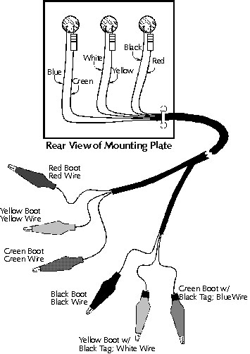
Step 5: Snap the LEDs into the holes you drilled, and solder the wires to the LEDs and resistors, as shown in the graphic. After the solder cools, slide the shrink tubing over the soldered wires, and apply heat to shrink the tubing into place.
Step 6: Cut the phone cord to about 12."
Step 7: Strip the gray insulation back about 2" from the end of the phone cord. Slide the red, green and yellow wires into one length of 1/8" shrink tubing; slide the blue, black and white wires into a second length 1/8" shrink tubing. Heat the shrink tubing to hold the wires in place.
Step 8: Cut two 1/4" pieces of 1/4" shrink tubing, and place one on one of the yellow alligator clip boots, and the other on one of the green alligator clip boots. You'll use these bands to identify the clips to connect when checking a transmission.
Step 9: Strip the colored ends of the individual wires about 3/8." Slide the boots over the appropriate wires, as shown in the graphic, and solder the alligator clips onto the wire ends. Wait till the solder cools before sliding the boots over the clips.
Step 10: Paint the back of the LEDs black, to prevent sunlight from shining through.
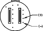
![]() The directions in this book for connecting your shift signal monitor are based on the wire and boot colors indicated in this drawing. Any deviation from these colors could affect your monitor's effectiveness and the results of your tests.
The directions in this book for connecting your shift signal monitor are based on the wire and boot colors indicated in this drawing. Any deviation from these colors could affect your monitor's effectiveness and the results of your tests.
Two Types of Wiring
That's because some systems supply power to energize the shift solenoids, and other supply ground. And, while your signal monitor works equally well on both systems, there's a difference in how you have to connect it to the harness.
The first system is where the computer supplies power to energize the solenoids. This system only requires the manufacturer to use one wire for each solenoid. The solenoids receive ground through the transmission case.
For these units, you'll connect the clips with the red, yellow and green boots to the solenoid wires.
You have to connect the other three clips to a good ground.
The other type of system is where the solenoids receive power from an external source, and the computer supplies ground to energize the solenoids.
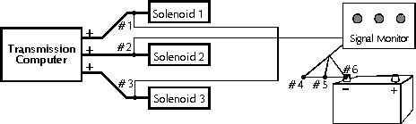
Signal Monitor Wire and Terminal Identification
#1 = Red Boot
#2 = Yellow Boot
#3 = Green Boot
#4 = Black Boot
#5 = Yellow Boot w/Black Band
#6 = Green Boot w/Black Band
For these units, you'll connect the clips with the red, yellow and green boots to a 12-volt power source; the other three clips connect to the individual solenoid wires.

If the computer supplies ground to energize the solenoid,
you'll connect the clips with the red, yellow and green boots to a good ground.
Comparing Your Results
![]() When connecting your signal monitor to the transmission connector, make sure you adjust the clips so they won't short against one another. Try connecting some to the transmission connector, and others to the harness connector. And always make sure the rubber boots are in place.
When connecting your signal monitor to the transmission connector, make sure you adjust the clips so they won't short against one another. Try connecting some to the transmission connector, and others to the harness connector. And always make sure the rubber boots are in place.
Once you have your signal monitor connected, route the wire through the back of the hood, and into the passenger compartment. Then close the hood, and go for a drive. The LEDs on your signal monitor should begin to light, to indicate the signals from the computer.
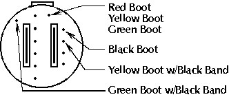
Here's an example of a connection graphic, which shows how to connect
your shift monitor to the transmission connector. This one's for a GM 4L60E.
To help you see whether the signals are correct, we've also included a chart for each transmission, indicating the signals you should see for each gear range. If the LEDs light to match the pattern in the chart for that transmission, the computer is providing the proper signals to the transmission.
But if the signals differ from those on the chart, the computer signals aren't correct; look for a computer system problem.
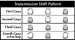
The computer signals should match the shift pattern listed in the chart
for the trasmission you're working on. This example is for a GM 4L60E.
Not Just for Shift Signals
But that's not all it does. You can use your signal monitor to examine any electrical signal the computer develops to control transmission operation. Another example of one of those signals is the pulsed signal the computer uses to control mainline pressure on a transmission with an electronic pressure control (EPC) solenoid.
These systems vary the ratio of on-time to off-time to control line pressure: The longer the solenoid is on, the lower pressure should be. So you can see whether the computer is controlling line pressure properly by looking for a change in the EPC signal as you vary the load on the engine.
Just connect the wires from one of the LEDs on your signal monitor to the EPC terminals. Your book identifies these terminals, and shows which is positive and which is negative.
You can even use your signal monitor to check the signals to the EPC solenoid.
Then drive the car. The LED should be dimmer than when checking a shift solenoid, because the signal is pulsing. The more load you put on the vehicle, the dimmer the LED should become. At full throttle, the LED should go out.
Now that you have your signal monitor built, and you're familiar with how to use it, you're ready to begin your diagnoses. The rest of this book provides the information you need to diagnose most domestic transmissions, using the skills you've learned in this program.
PAGE 19-24