Chapter 4
Ford's Transmissions
and Transaxles
|
|
|
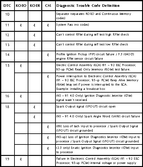
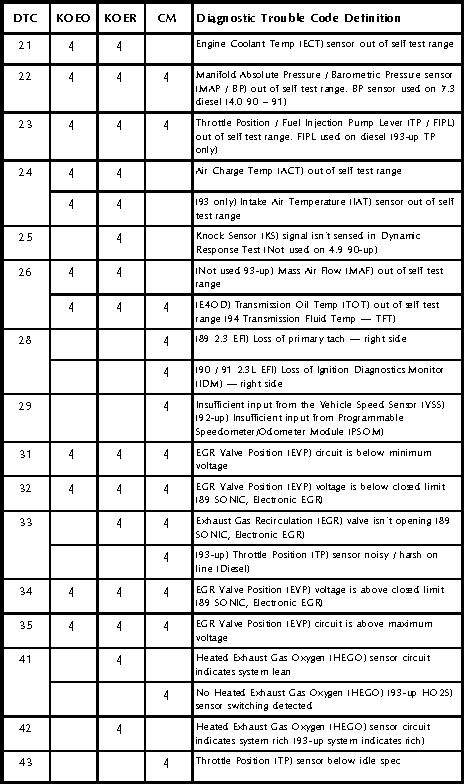
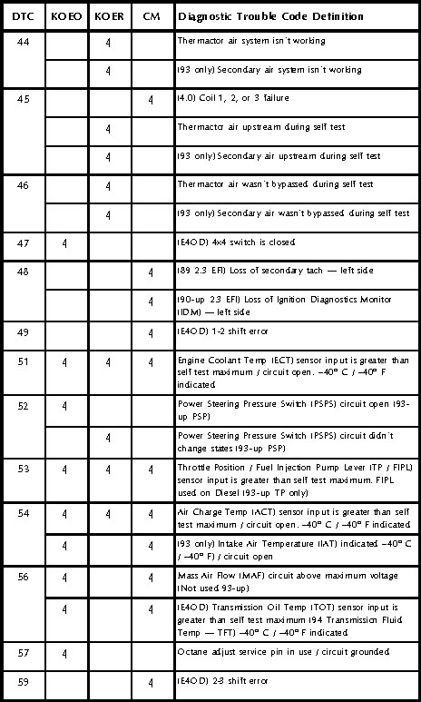
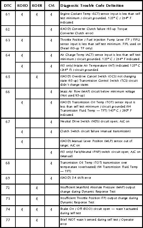
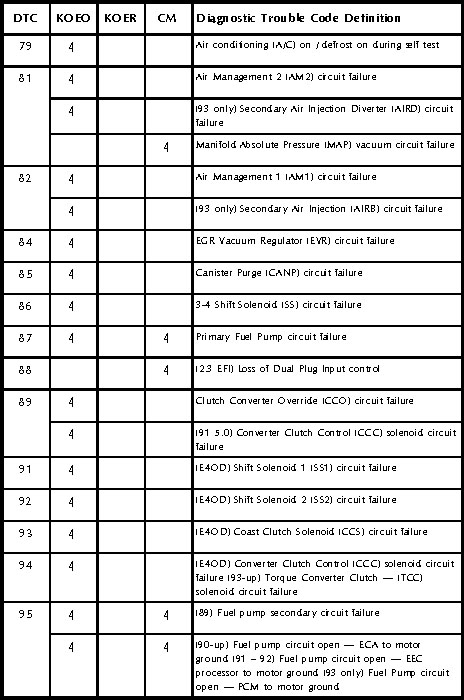
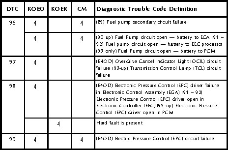
The charts on the next few pages provide all of the diagnostic trouble codes for Ford vehicles, up to the introduction of OBD-II. Many of these codes vary their definition, depending on vehicle year or model. If you arenít sure what condition one of these codes indicates, always check your shop manual for the specific year, make and model vehicle youíre working on.
The two-digit code definitions also depend on what type of code youíre looking at: KOEO On-Demand, KOER On-Demand, or Continuous Memory. These charts indicate which type of code each definition applies to; make sure youíre using the right definition before beginning your diagnosis.
Two-Digit Codes
Three-Digit Codes
Code Description
111 System passed.
112** Air charge temperature sensor or vane air temperature sensor circuit grounded.
113** Air charge temperature sensor or vane air temperature sensor circuit open.
114 Air charge temperature sensor or vane air temperature sensor voltage out of range.
116 Engine temperature sensor voltage out of range.
117** Engine temperature sensor circuit grounded.
118** Engine temperature sensor circuit open.
121 Throttle position sensor voltage out of range or inconsistent with MAF sensor.
122 Throttle position sensor voltage low.
123** Throttle position sensor voltage high.
124** Throttle position sensor voltage higher than expected.
125** Throttle position sensor voltage lower than expected.
126** MAP sensor signal out of range.
128** MAP sensor vacuum hose damaged or disconnected.
129 MAP or mass airflow sensor change insufficient during dynamic response test.
136 Oxygen sensor isnít switching ó indicates lean exhaust, left side.
137 Oxygen sensor isnít switching ó indicates rich exhaust, left side.
139** Oxygen sensor isnít switching ó left side. (í90 vehicles have only one oxygen sensor.)
144** Oxygen sensor isnít switching ó right side. (í90 vehicles have only one oxygen sensor.)
157** Mass airflow sensor voltage below minimum.
158** Mass airflow sensor voltage above maximum.
159 Mass airflow sensor voltage higher or lower than expected.
167 Throttle position change insufficient during dynamic response test.
171** Fuel system at adaptive limit; Right side oxygen sensor isnít switching. (í90 vehicles have only one oxygen sensor.)
172** Oxygen sensor signal lean ó right side. (í90 vehicles have only one oxygen sensor.)
173** Oxygen sensor signal rich ó right side. (í90 vehicles have only one oxygen sensor.)
174** Oxygen sensor switching slowly.
175** Fuel system at adaptive limit; Left side oxygen sensor isnít switching. (í90 vehicles have only one oxygen sensor.)
176** Oxygen sensor signal lean ó left side. (í90 vehicles have only one oxygen sensor.)
177** Oxygen sensor signal rich ó left side. (í90 vehicles have only one oxygen sensor.)
179** Fuel system at lean adaptive limit at part throttle (exhaust rich).
181** Fuel system at rich adaptive limit at part throttle (exhaust lean).
182** Adaptive fuel lean limit reached at idle.
183** Adaptive fuel rich limit reached at idle.
184** Mass airflow sensor voltage high.
185** Mass airflow sensor voltage low.
186** Vehicles with barometric pressure sensor: Injector pulse width higher than expected.
187** Vehicles with barometric pressure sensor: Injector pulse width lower than expected or mass airflow sensor lower than expected; Vehicles without barometric pressure sensor: Injector pulse width lower or mass airflow sensor higher than expected.
188** Fuel system at lean adaptive limit at part throttle (exhaust rich).
189** Fuel system at rich adaptive limit at part throttle (exhaust lean).
191** Fuel system at lean adaptive limit at idle (exhaust rich).
192 Fuel system at rich adaptive limit at idle (exhaust lean).
193 Flexible fuel sensor circuit failure
211 Profile ignition pickup (PIP) circuit failure.
212 Tach input missing to computer; ignition diagnostic monitor (IDM) input to computer or SPOUT circuit grounded.
213 SPOUT circuit open.
214 Cylinder identification circuit failure.
215** Coil #1 primary circuit failure.
216** Coil #2 primary circuit failure.
217** Coil #3 primary circuit failure.
218** Ignition diagnostic monitor (IDM) signal lost ó left side.
219 SPOUT circuit open ó spark timing held at 10į.
221 Spark timing error.
222** Ignition diagnostic monitor (IDM) signal lost ó right side.
223** Dual plug inhibit control lost.
224** Coil 1, 2, 3 or 4 primary circuit failure.
225 Knock not detected during dynamic response test.
226 Ignition diagnostic monitor (IDM) signal not received.
227 Crankshaft position sensor error.
232** Coil 1, 2, 3 or 4 primary circuit failure.
233 Spark angle pulse width error.
238** Coil #4 primary circuit failure.
239 Crankshaft position signal received with engine off.
241 EDIS to computer ignition diagnostic monitor (IDM) pulse width transmission error.
242 Operating in DIS failure mode.
243 Secondary circuit failure.
311 AIR system wasnít working during self test ó right side with dual oxygen sensors.
312 AIR misdirected during self test.
313 AIR wasnít bypassed during self test.
314 AIR system wasnít working during self test ó left side with dual oxygen sensors.
326 EGR (EPT/PFE/DPFE) circuit voltage lower than expected.
327** EGR (EGRP/EVP/EPT/PFE/DPFE) circuit below minimum voltage.
328 Exhaust pressure high; EGR (EVP) voltage lower than expected.
332** EGR valve opening not detected by sensor or insufficient EGR flow detected.
334 EGR (EVP) higher than expected with EGR closed.
335 EGR (EPT/PFE/DPFE) sensor voltage out of range during self test.
336 Exhaust pressure high; EGR (EPT/PFE/DPFE) voltage higher than expected.
337** EGR (EGRP/EVP/EPT/PFE/DPFE) circuit voltage too high.
341 Octane adjust service pin in use.
338 Engine coolant temperature lower than expected during the thermostat test.
339 Engine coolant temperature higher than expected during the thermostat test.
381 A/C clutch cycling too often.
411 RPM out of control during self test low RPM check.
412 RPM out of control during self test high RPM check.
415 Idle air control (IAC) system at adaptive lower learning limit.
416 Idle air control (IAC) system at upper adaptive learning limit.
452 Vehicle speed sensor input too low.
453 Servo leaking down.
454 Servo leaking up.
455 RPM increase insufficient.
456 RPM decrease insufficient.
457 Speed control command switch circuit not working.
458 Speed control command switch stuck or circuit grounded.
459 Speed control ground circuit open.
511 Computer read only memory (ROM) test failed.
512 Computer keep-alive memory (KAM) test failed.
513 Computer internal voltage failure.
519 Power steering pressure switch open.
521* Power steering pressure switch didnít change states.
522 Transmission not in park or neutral during self test; PNP switch circuit open.
524 Low speed fuel pump circuit open from battery to computer.
525 Vehicle was in gear or A/C was on during self test.
528* Clutch pedal position switch circuit failure.
529 Data communication link or computer failure.
532 Cluster control assembly circuit failure.
533 Data communication link or electronic instrument cluster circuit failure.
536* Brake on/off circuit failure; not actuated during self test.
538* Operator error ó computer didnít perform dynamic response test or cylinder balance test properly, or cylinder balance failed because throttle moved or cylinder ID sensor failed.
539 A/C or defrost on during self test.
542 Fuel pump circuit open from computer to motor ground; fuel pump secondary circuit failure.
543 Fuel pump circuit open from battery to computer; fuel pump secondary circuit failure.
551 Idle air control (IAC) circuit failure.
552 Air management circuit #1 failure ó secondary air injection bypass.
553 Air management circuit #2 failure ó secondary air injection diverter.
555 Supercharger bypass solenoid circuit failure.
556 Primary fuel pump circuit failure.
557 Low speed primary fuel pump circuit failure.
558 EGR vacuum regulator circuit failure.
559 Air conditioning on relay circuit failure.
562 Auxiliary electrodrive fan circuit failure.
563 High speed fan circuit failure.
564 Fan control circuit failure.
565 Canister purge circuit failure.
566 3-4 shift solenoid circuit failure.
567 Speed control vent circuit failure.
568 Speed control vacuum circuit failure.
569 Auxiliary canister purge circuit failure.
571 EGRA solenoid circuit failure.
572 EGRV solenoid circuit failure.
578 A/C pressure sensor circuit shorted.
579 A/C pressure change insufficient.
581 Power to fan circuit over current.
582 Fan circuit open.
583 Power to fuel pump over current.
584 VCRM power ground circuit open.
585 A/C clutch circuit over current.
586 A/C clutch circuit open.
587 Variable control relay module communication failure.
617 1-2 shift error.
618 2-3 shift error.
619 3-4 shift error.
621 Shift solenoid circuit #1 failure.
622 Shift solenoid circuit #2 failure.
623 Transmission control switch circuit didnít change states during self test.
624 Electronic pressure control circuit failure.
625 Electronic pressure control driver open in computer.
626 Coast clutch solenoid circuit failure.
627 Torque converter clutch control solenoid circuit failure.
628 Converter clutch has too much slip or error.
629 Torque converter clutch control solenoid circuit failure.
631 Overdrive cancel indicator light or transmission control indicator lamp circuit failure.
632* Overdrive cancel switch circuit or transmission control switch circuit didnít change states during self test.
633 4x4 switch closed during self test.
634 Manual lever position switch sensor or transmission range out of range. Code may also set if A/C switch was on during self test.
636 Transmission fluid temperature sensor voltage out of range.
637 Transmission fluid temperature sensor circuit voltage too high or open.
638 Transmission fluid temperature sensor circuit voltage too low or grounded.
639 Turbine/transmission speed sensor input too low.
641 Shift solenoid #3 circuit failure.
643 Torque converter clutch circuit failure.
645 1st gear ratio incorrect.
646 2nd gear ratio incorrect.
647 3rd gear ratio incorrect.
648 4th gear ratio incorrect.
649 Electronic pressure control higher or lower than expected.
651 Electronic pressure control circuit failure.
652 Modulated lockup solenoid circuit failure or torque converter clutch control solenoid circuit failure.
653* Transmission control switch didnít change states during self test.
654 Manual lever position sensor or transmission range sensor didnít indicate park during self test.
656 Torque converter clutch continuous slip error.
657 Transmission over temperature condition occurred.
659 High vehicle speed in park detected.
667 Transmission range sensor circuit voltage too low.
668 Transmission range sensor circuit voltage too high.
675 Transmission range sensor circuit voltage out of range
998 Hard fault present ó computer in FMEM (alternate strategy) mode.
|
* |
You may have to perform certain steps during self test or a "you blew it" code may appear. A "you blew it" code could also occur from performing the self test on an engine below operating temperature, or wasn't run at 2000 RPM for two minutes to warm the oxygen sensor. |
|
** |
Indicates the engine control system goes into FMEM (alternate strategy) when this code sets. |